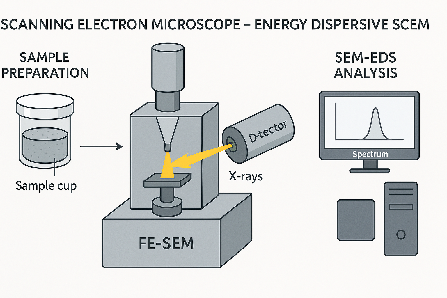
The Scanning Electron Microscope energy dispersive X-ray spectroscopy (SEM-EDS) Phenom Prox model, manufactured by phenomWorld Eindhoven, Netherlands was used to carry out the morphology analysis. Sample is placed on the Aluminium holder stub using sticky carbon tape. The sample was insulated using gold and then grounded electrically. The samples each are then labeled on their stub, then dried in the oven at 60oC. Nitrogen line was opened at 50 psi and the vent button is pressed to fill the area with nitrogen for proper purging of the chamber. The sample holder stub was then placed in the sample chamber holes and the door was shut and the rotary pump picked and a vacuum of 5 x 10⁻⁵ Pa was created. The filament light was switched on and the monitor too automatically switched on. At this stage, the accelerator voltage was 15kV and the filament burned out. The atoms on the surface are excited by the electron beam, emitting specific wavelengths of X-rays that are characteristic of the atomic structure of the elements. An energy dispersive detector (a solid-state device that discriminates among X-ray energies) can analyze these X-ray emissions. Appropriate elements are assigned, yielding the composition of the atoms on the specimen surface. The lowest scan mode of 10x is picked and the TV scan clicked. The magnification is then taking to 1000x at a slow scan, 2000, 3000 to 5,000. The Energy dispersion spectrum scan on the intensity of each of the element present and gives the molar concentration in %, then Image was saved. This procedure is called The Scanning Electron Microscope Energy dispersive X-ray spectroscopy (SEM-EDS) and is useful for analyzing the composition of the surface of a specimen
Sample Preparation
Metallic Samples have a certain affinity for the electromagnets within the SEM. This affinity may be strong enough to pull the sample from the stub and up into the detector region. This will cause degradation of imaging capability and will require a service technician to remove this material from the detector. To avoid this scenario, the sample was firmly fastened to the SEM stub
Loading samples
It was ensured that the sample was properly mounted and immobilized on the stub. The height adjustment ring of the sample holder was turned counter-clockwise until the mounting surface is in the highest position and the stub pin was inserted into the hole on the mounting surface, using the tweezers. Also, it was ensured that the stub was inserted in such way that the flat of the stub is seated on the mounting surface. The sample was lowered by turning the height adjustment ring clockwise the sample was positioned correctly as it was at 2 mm below the top surface of the holder, since each one of the vertical marks on the adjustment ring corresponds to 0.5 mm, thus, rotating the adjustment ring by 4 marks lowered the sample by 2 mm. The best resolution was obtained when the sample is positioned 2 mm below the holder surface. The holder surface allows the user to optimize the trade-off between maximum field-of-view (minimum magnification) and image resolution (maximum useful magnification).
The door was opened by pushing the handle upward. The handle was held and the door was raised to its fullest extent and the sample was inserted into the sample holder slot. The sample holder was inserted correctly when the SAMPLE LED lights up green and the message ‘Please load sample’ disappears from the Image screen. The door was closed by sliding it down firmly with little initial force. The door locked automatically when a‘ lights up orange came up, then the sample is loaded and ready for imaging. The Phenom was re-activated and the sample automatically moved to the optical imaging position without sample holder inserted OK button was clicked to confirm The sample holder was then activated and its name was displayed when the holder is inserted.
Optical imaging
After the Phenom door was closed, the sample was transferred automatically to the optical imaging position. The optical camera was activated and the image was displayed in the main viewing window of the Image screen. The part of the sample that was magnified in the main viewing window was displayed in the optical overview window.
Adjusting focus
Touch to activate focus adjustment.
A focus slider appeared, showing the current focus setting. Rotate the rotary knob was rotated to adjust the focus of the optical image. Adjustment was made visible by the slider. the rotary knob was then pressed to select fine focus. An ‘F’ appears on the button and focus adjustment then took in small steps. The rotary knob was pressedagain to return to normal (coarse) focus.
Adjusting magnification (ProX / Pro)
A magnification slider showing the current magnification setting was pressed and the rotary knob was pressed to adjust the magnification of the optical image. The adjustment was made visible by the slider.
Storing images
Images was stored on a USB 2.0 flash drive (USB Flash drive) as well as on Windows.
Selecting storage location
When a USB Flash drive is inserted into one of the Phenom USB ports from SETTINGS in the screen selection bar, the Settings screen appears and the USB was cliked then the images was stored on the USB 2.0 flash drive.